| & |
Pinout - Logic
|
PIN |
Default State |
Description |
|
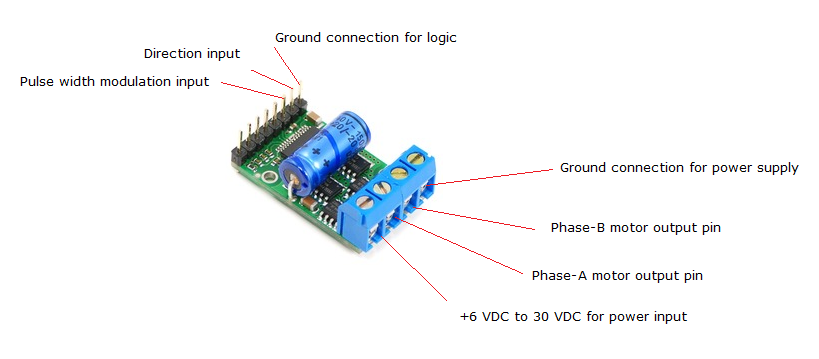
GND |
|
Ground
connection for logic |
|
PWM |
LOW |
Pulse width
modulation input: a PWM signal on this pin
corresponds to a PWM output on the motor
outputs |
|
DIR |
FLOAT |
Direction
input: when DIR is high current will flow
from OUTA to OUTB, when it is low current
will flow from OUTB to OUTA |
Pinout
- Power
|
PIN |
Description |
|
V+ |
+6 VDC to 30 VDC for power input |
|
GND |
Ground
connection for power
supply |
|
OUTA |
Phase-A motor output
pin |
|
OUTB |
Phase-B motor output
pin |
|